Prepare the mix
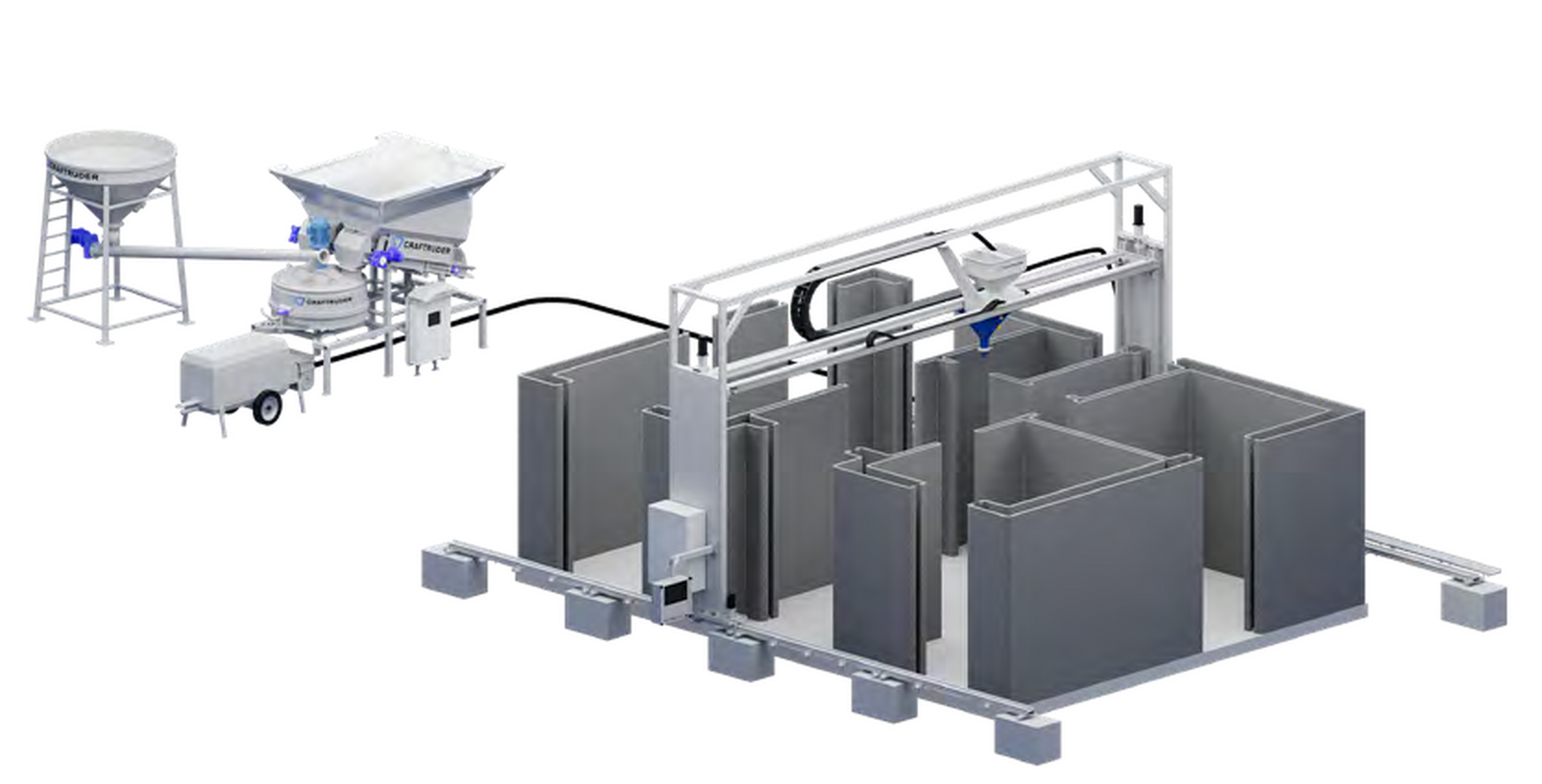
A concrete batching plant prepares the printing material using a mix design adapted to available local constituents.
 REQUEST A PROPOSAL
OUTDOOR / ON-SITE
The on-site house printing system combines a gantry construction 3D printer, single extrusion module, batching equipment and concrete pump for programmed wall construction at the project location.
SITE WORKFLOW
On-site printing requires more than the gantry. Material preparation, delivery, print-path planning and a prepared foundation operate as one system.
A concrete batching plant prepares the printing material using a mix design adapted to available local constituents.
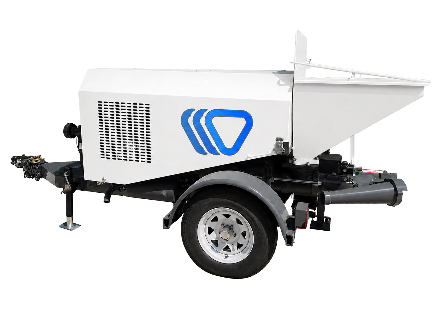
For outdoor operation, a concrete pump and delivery line replace the fixed factory conveyor and move material to the extruder.
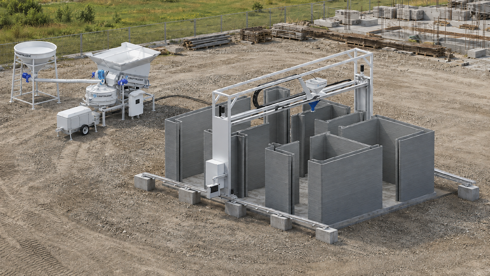
The CNC-controlled gantry follows programmed geometry and deposits each layer directly over the prepared construction footprint.
DIRECTLY ON THE FOUNDATION
A single extruder and flexible print-path programming allow the machine to produce straight and curved walls directly in their final position. The printed shell is then integrated with reinforcement, insulation, openings and the remaining building systems.
MATERIAL DELIVERY
The pump configuration keeps the material source outside the gantry workspace while supplying the moving print system. Final pump selection and line arrangement depend on the mix, site layout and required delivery distance.
PRINTING ENVELOPE
The standard platform provides a 12-metre longitudinal axis, a 5-metre transverse printing width and 1.2 metres of vertical travel. Extensions are configured around the intended building geometry.
DESIGN AND OUTPUT
The printer can form a decorative layered surface on both sides of the wall and follow flexible paths. Actual output is calculated for the specific geometry and production plan.
The wall shell is printed at its final position, avoiding a separate transport stage for large prefabricated wall sections.
Digital geometry supports straight and curved wall paths within the configured printing envelope.
Output depends on layer parameters, geometry, pauses, non-printing travel, material behaviour and shift organisation.